To avoid damaging the quick connector, place a towel or cloth in the groove joint pliers jaw, figure 7.
Note: Using a towel offers better grip
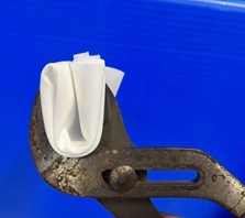
Figure 7. A towel in the groove joint pliers jaw.
2. Firmly place the groove joint pliers jaw under the neck of the quick disconnect fitting, Figure 8.
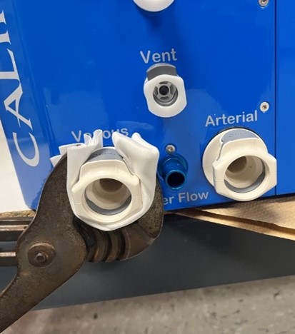
Figure 8. Pliers with towel placed under the neck of the quick disconnect fitting.
3. Use the adjustable plier to secure the white bushing in place, circled red in Figure 9.
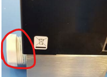
Figure 9. Location of the white bushing hex nut inside the CPM
4. Loosen the ½” Venous Quick disconnect fitting with the Groove Joint Pliers. Manually remove the fitting once it’s loose enough.
Note: Exercise caution in applied grip force as the connector can crack
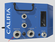
Figure 10. Location of the Venous quick disconnect fitting
e. Service quick connector
i. Clean thread end from any debris
ii. Apply 8 inches of Teflon tape to pipe thread
1. Tape in the direction shown in Figure 11
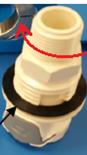
Figure 11. Direction to apply Teflon tape
f. Install quick connector
i. Loosen the valve base screws (one on either side) so valve is allowed to slide, Figure 12.
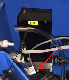
Figure 12. Location of the valve base screws
i. Place quick connector through panel hole
ii. Insert the grey plastic hex nut (do not tighten yet)
iii. Thread into white bushing – do most of this by hand, use the Groove Joint Pliers with a wrapped cloth to complete the last turn
Note: Since valve base is loose, valve may slide a bit as the quick disconnect fitting is tightened, this sliding is fine.
g. Secure grey hex nut and valve base screws
h. Insert Overflow port through panel hole and secure with two 2 mm hex flathead screws
i. Insert ¼” quick connector through Vent hole, secure with hex nut, insert tubing and wiggle pinch clamp onto barbed section of tubing
j. Insert ¼” quick connector through Cardioplegia hole, secure hex nut, insert tubing and wiggle pinch clamp onto barbed section of tubingMount top cover and secure with all hex screws
k. Run water through CPM plumbing and ensure leak has been fixed